Isometric Style Configuration - Rolling Offset Depiction
The configurations
in this option (shown below) define the settings for a rolling offset. A
rolling offset refers to a directional change (both vertically and
horizontally) a pipe can make in a piping system. In a rolling offset:
When finished making any changes in the fields, click
Save to apply the changes.
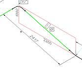
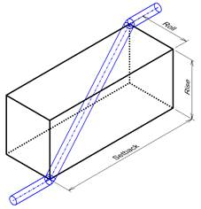
The image below provides a good visualization of how the offset is depicted in a model:
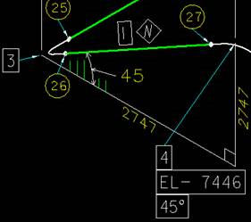
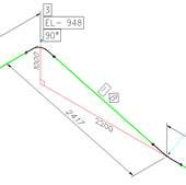
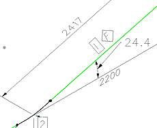
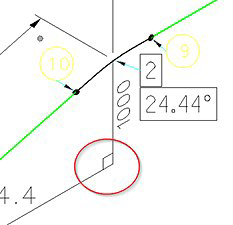
When an isometric is created offsets are depicted using hatched triangles/boxes such as the one shown below:

The settings below define how the rolling offsets are represented in the isometric.
Note: To apply the
settings to a previously generated isometric, the user will need to save the
Style Configuration settings and regenerate the isometric(s).

| Setting | Description |
|---|---|
| Hatch Properties | Hatching rolling offset triangles can be done in the
following ways:
|
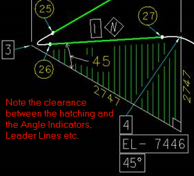
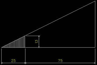
| Partial Hatch Options | When the Partial Hatch option is selected, the
following options determine how the partial hatching is to be applied in the
isometric.
|
| Hatch Symbology | This Symbology defines settings for a hatch line.
|
| Triangle/Box Properties | The options in this section determine how offsets are
depicted in the isometric.
|
| Angle Annotation |
|
| Triangle Symbology |
|